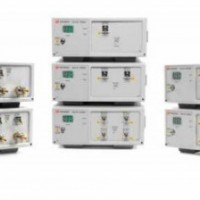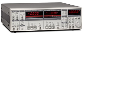
srs SR830-100 kHz DSP lock-in amplifier
srs SR830-100 kHz DSP lock-in amplifier
"主要指标与说明The SR810 Lock-In Amplifier and SR830 Lock-In Amplifier provide high performance at a reasonable cost. The SR830 simultaneously displays the magnitude and phase of a signal, while the SR810 displays magnitude only.
Both instruments use digital signal processing (DSP) to replace the demodulators, output filters, and amplifiers found in conventional lock-ins.""1 mHz to 102.4 kHz range
>100 dB dynamic reserve
5 ppm/°C stability
0.01 degree phase resolution
Time constants from 10 µs to 30 ks
(up to 24 dB/oct rolloff)
Auto-gain, -phase, -reserve and -offset
Reference source
GPIB and RS-232 interfacesSR810 and SR830 Lock-In Amplifiers
The SR810 Lock-In Amplifier and SR830 Lock-In Amplifier provide high performance at a reasonable cost. The SR830 simultaneously displays the magnitude and phase of a signal, while the SR810 displays magnitude only. Both instruments use digital signal processing (DSP) to replace the demodulators, output filters, and amplifiers found in conventional lock-ins. The SR810 and SR830 provide uncompromised performance with an operating range of 1 mHz to 102 kHz and 100 dB of drift-free dynamic reserve.
Input Channel
The SR810 and SR830 Lock-In Amplifiers h**e differential inputs with 6 nV/√Hz input noise. The input impedance is 10 MΩ, and minimum full-scale input voltage sensitivity is 2 nV. The input can also be configured for current measurements with selectable current gains of 106 and 108 V/A. A line filter (50 Hz or 60 Hz) and a 2× line filter (100 Hz or 120 Hz) are provided to eliminate line related interference. However, unlike conventional lock-in amplifiers, no tracking band-pass filter is needed at the input. This filter is used by conventional lock-ins to increase dynamic reserve. Unfortunately, band pass filters also introduce noise, amplitude and phase error, and drift. The DSP based design of these lock-ins has such inherently large dynamic reserve that no tracking band-pass filter is needed.Extended Dynamic Reserve
The dynamic reserve of a lock-in amplifier at a given full-scale input voltage is the ratio (in dB) of the largest interfering signal to the full-scale input voltage. The largest interfering signal is defined as the amplitude of the largest signal at any frequency that can be applied to the input before the lock-in cannot measure a signal with its specified accuracy.
Conventional lock-in amplifiers use an analog demodulator to mix an input signal with a reference signal. Dynamic reserve is limited to about 60 dB, and these instruments suffer from poor stability, output drift, and excessive gain and phase error. Demodulation in the SR810 Lock-In Amplifier and SR830 Lock-In Amplifier is accomplished by sampling the input signal with a high-precision A/D converter, and multiplying the digitized input by a synthesized reference signal. This digital demodulation technique results in more than 100 dB of true dynamic reserve (no prefiltering) and is free of the errors associated with analog instruments.
Digital Filtering
The digital signal processor also handles the task of output filtering, allowing time constants from 10 µsec to 30,000 s, with a choice of 6, 12, 18 and 24 dB/oct rolloff. For low frequency measurements (below 200 Hz), synchronous filters can be engaged to notch out multiples of the reference frequency. Since the harmonics of the reference h**e been eliminated (notably 2F), effective output filtering can be achieved with much shorter time constants.
""Reference Channel
Frequency range 0.001 Hz to 102.4 kHz
Reference input TTL or sine (400 mVpp min.)
Input impedance 1 MΩ, 25 pF
Phase resolution 0.01° front panel, 0.008° through computer interfaces
Absolute phase error<1°
Relative phase error<0.001°
Orthogonality 90° ± 0.001°
Phase noise
Int. reference Synthesized,<0.0001° rms at 1 kHz
Ext. reference 0.005° rms at 1 kHz, 100 ms, 12 dB/oct
Phase drift<0.01°/°C below 10 kHz,
<0.1°/°C, 10 kHz to 100 kHz
Harmonic detection 2F, 3F, ... nF to 102 kHz (n < 19,999)
Acquisition time (2 cycles + 5 ms) or 40 ms, whichever is greaterDemodulator
Stability Digital outputs and display: no drift. Analog outputs:<5 ppm/°C for all dynamic reserve settings.
Harmonic rejection -90 dB
Time constants 10 µs to 30 ks (6, 12, 18, 24 dB/oct rolloff). Synchronous filters **ailable below 200 Hz.
Internal Oscillator
Range 1 mHz to 102 kHz
Accuracy 25 ppm + 30 µHz
Frequency resolution 4½ digits or 0.1 mHz, whichever is greater
Distortion -80 dBc (f
Amplitude 0.004 to 5 Vrms into 10 kΩ (2 mV resolution), 50 Ω output impedance, 50 mA maximum current into 50 Ω
Amplitude accuracy 1 %
Amplitude stability 50 ppm/°C
Outputs Sine, TTL (When using an external reference, both outputs are phase locked to the external reference.)Displays
Channel 4½-digit LED display with 40-segment LED bar graph. X, R, X-noise, Aux 1 or Aux 2. The display can also be any of these quantities divided by Aux 1 or Aux 2.
Channel 2 (SR830) 4½-digit LED display with 40-segment LED bar graph. Y, Θ, Y-noise, Aux 3 or Aux 4. The display can also be any of these quantities divided by Aux 3 or Aux 4.
Offset X, Y, R can be offset up to ±105 % of full scale.
Expand X, Y, R can be expanded by 10× or 100×.
Reference 4½-digit LED display
Inputs and Outputs
CH1 output ±10 V output of X, R, X-noise, Aux 1 or Aux 2. Updated at 512 Hz.
CH2 output (SR830) ±10 V output of Y, Θ, Y-noise, Aux 3 or Aux 4. Updated at 512 Hz.
X, Y outputs In-phase and quadrature components
(rear panel) (±10 V), updated at 256 kHz
Aux. A/D inputs 4 BNC inputs, ±10 V, 1 mV resolution, sampled at 512 Hz
Aux. D/A outputs 4 BNC outputs, ±10 V, 1 mV resolution
Sine Out Internal oscillator analog output
TTL Out Internal oscillator TTL output
Data buffer The SR810 has an 8k point buffer. The SR830 has two 16k point buffers. Data is recorded at rates to 512 Hz and read through the computer interfaces.
Trigger In (TTL) Trigger synchronizes data recording
Remote pre-amp Provides power to the optional SR550, SR552 and SR554 preamplifiers
General
Interfaces IEEE-488.2 and RS-232 interfaces standard. All instrument functions can be controlled and read through IEEE-488.2 or RS-232 interfaces.
Power 40 W, 100/120/220/240 VAC, 50/60 Hz
Dimensions 17"" × 5.25"" × 19.5"" (WHL)
Weight 23 lbs.
Warranty One year parts and labor on defects in materials and workmanship
"